Ports and berths are subjected to a variety of forcings that may be originated by soil pressure (also induced by vehicles), waves and forcings induced by ships. Forcing estimation on a berth is not an easy task as some processes generating forces may be inherently random. Design needs to be based on extreme conditions that are usually assessed by analysing observations.
We will not focus on forcing from land such as soil pressure, traffic load and shear stresses on berth structure induced by land-side processes. Also, we will not focus on gravity walls, cut-off and sheet pile design. Gravity walls and sheet piles are often used to build berth walls and therefore are relevant to harbour engineering. However, forcings from land and retention structures are usually dealt with in geotechnical engineering. The interested reader may find an exhaustive treatment, from the perspective of harbor engineering, in the Port designer's handbook.
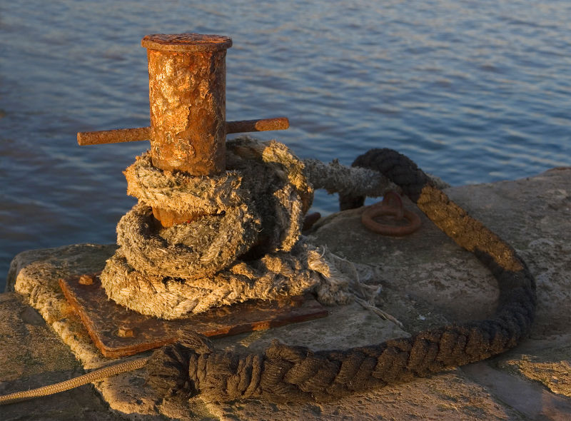
Figure 1. Mooring bollard at Lyme Regis, Dorset, UK. By MichaelMaggs - Own work, CC BY-SA 3.0, https://commons.wikimedia.org/w/index.php?curid=3684108
Knowledge of the terminology may be helpful to better understand the concepts below. An exhaustive glossary of nautical terms is given here.
Box 0: Nautical terms related to ship size
Main measurements used to characterise ship size are given in Figure B0.1. Dimension b is the beam. Length overall is o/a. Waterline length is w/l. Length between perpendiculars is p/p. Draught (draft) is d. Freeboard is f.

Figure B0.1. Graphical representation of the dimensions used to describe a ship. Dimension b is the beam. Length overall is o/a. Waterline length is w/l. Length between perpendiculars is p/p. Draught (draft) is d. Freeboard is f. By Emoscopes - Ship length measurements.png, CC BY-SA 3.0, https://commons.wikimedia.org/w/index.php?curid=19327377
A mooring system should permit the ship to remain safely moored to a pier under specified design loading conditions. Environmental forcing on a moored ship causes mooring loads. They may act through direct contact between the ship and the structure, contact through the fenders or through the tensioned mooring lines. Loads due to moored ship manouvers should also be considered. Mooring loads are caused by an external action that are acting on a moored ship. The load upon each mooring can be computed by studying the ship/mooring/fender system as a solid with elastic links, subject to dynamic response. In this lecture we will consider environmental loads due to:
- Wind;
- Waves;
- Currents.
We will not consider berth's load originated during berthing. These are due to the transfer to the moorings of the kinetic energy of manouvering ships, due to usual conditions and accidental events.
The following guidelines may be applied for a simplified approach to the computation of mooring loads. For design ships up to 20.000 t displacement, each mooring point can be designed so that it resists to the following minimum loads:
- Horizontal pull ranging from 10 to 100 t depending on ship displacement and type of load.
- Vertical pull of 0.5 the horizontal pull, acting at the same time.
Pull load should be considered occurring shipward at any angle with the berthing front, to select the most critical condition. For the design of the berth structure it should be assumed that load occurs at the same time in all the mooring points. The latter should be spaced between 15 and 30 meters.
For design ships of more than 20.000 t displacement the assessment of the mooring loads should be carried out by considering all possible forcings. Here below we propose a brief discussion of the loads given by wind, waves and currents. Further details are given by Spanish standard ROM 0.2-90 (Ministerio de Obras Públicas y Transportes, 1990).
Wind forces originate pressure over the body of ships. As such they are relevant for designing moors and berths. Wind forces are generally more important with respect to forcings originated by waves and currents, that will be treated later.
Winds are usually characterised by the wind rose, namely, a graphical representation of how wind speed and direction are distributed at a particular location. Data to estimate the wind rose is usually taken by an anemometer. For berth design we use anometers placed at 10 m above ground. The longer the length of the historical wind record the more reliable the wind rose is. Observations are to be quality checked and stationarity of climate is frequently assumed.
The frequency of winds over an assigned time period is plotted by wind direction, with colour bands showing wind speed ranges. Figure 2 shows the wind rose plot for the La Guardia Airport in New York (2008). Prevailing winds in this case are Southerly and North-Westerly. The length of each "spoke" is related to the frequency a given wind blows per unit time. Each concentric circle represent a frequency, from the null value at the centre of the wind rose and increasing frequency for increasing distance from the centre.
For an assigned direction - for instance South in Figure 2 - the wind rose gives the frequency (percentage of time) wind blows in that direction and the color codes depict the intervals of frequency each velocity range blows in. The color bar on the right in Figure 2 also indicates the average frequency each velocity range occurs. Percentages in the color band indicate the frequency of time each velocity range is observed over the whole range of directions. They do not sum precisely to 100 % as winds that do not fall in the considered ranges are sporadically observed. In the light blue circle at the centre of the rose the frequency of calm conditions is indicated.
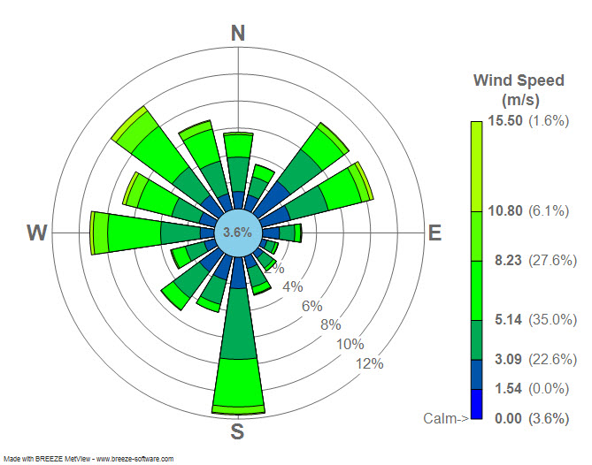
Figure 2. Wind rose plot for LaGuardia Airport (LGA), New York, 2008. BREEZE Software [CC BY-SA (http://creativecommons.org/licenses/by-sa/3.0/)].
For an assigned direction, the wind rose allows one to depict the probability distribution of wind velocity. For instance, along the South direction in Figure 2 one can see that wind velocity of 3 m/s is not exceeded about 2+3.6% of time (where 3.6% refers to calm conditions). Similarly, velocities of about 5 m/s, 8 m/s and 11 m/s are not exceed about 8+3.6%, 11.5+3.6% and 11.8+3.6% of time. Figure 3 shows the corresponding cumulative probability distribution. The scale along the vertical axis spans from 0 to about 15.6 %, namely, from 0 to the percentage of time with calm conditions and wind blowing along the South direction. Note that "percentage of time" is equivalent to frequency and therefore a good estimate of cumulative probability of a given wind velocity range.

Figure 3. Cumulative probability distribution of wind velocity in the South direction at La Guardia.
Box 1: Probability
Probability describes the likelihood of an event. Probability is quantified as a number between 0 and 1 (where 0 indicates impossibility and 1 indicates certainty). The higher the probability of an event, the higher the likelihood that the event will occur. Probability may be defined through the Kolmogorov axioms:
- Axiom 1: The probability of an event is a real number greater than or equal to 0.
- Axiom 2: The probability that at least one of all the possible outcomes of a process (such as rolling a die) will occur is 1.
- Axiom 3: If two events A and B are mutually exclusive, then the probability of either A or B occurring is the probability of A occurring plus the probability of B occurring.
Probability may be estimated through an objective analysis of experiments, or through belief. This subdivision originates two definitions of probability. The frequentist definition is a standard interpretation of probability; it defines an event's probability as the limit of its relative frequency in a large number of trials. Such definition automatically satisfies Kolmogorov's axioms. The Bayesian definition associates probability to a quantity that represents a state of knowledge, or a state of belief. Such definition may also satisfy Kolmogorov's axioms, although it is not a necessary condition. Frequentist and Bayesian probabilities should not be seen as competing alternatives. In fact, the frequentist approach is useful when repeated experiment can be performed (like tossing a coin), while the Bayesian method is particularly advantageous when only a limited number of experiments, or no experiments at all, can be carried out. The Bayesian approach is particularly useful when a prior information is available, for instance by means of physical knowledge.
Probability distribution A probability distribution (or probability function) assigns a probability to a considered random event. To define a probability distribution, one needs to distinguish between discrete and continuous random variables. In the discrete case, one can easily assign a probability to each possible value, by means of intuition or by experiments. For example, when rolling a fair die, one easily gets that each of the six values 1 to 6 has equal probability that is equal to 1/6. One may get the same results by performing repeated experiments.
In the case a random variable takes real values, like for instance wave height, probabilities can be nonzero only if they refer to intervals. To compute the probability that the outcome from a real random variable falls in a given interval, one needs to define the probability density. Let us suppose that a interval with length 2Δx is centered around a generic outcome x of the random variable X, from the extremes x-Δx and x+Δx. Now, let us suppose that repeated experiments are performed by extracting random outcomes from X. The frequency of those outcomes falling into the above interval can be computed as:
Fr(x-Δx;x+Δx) = N(x)/N,
where N(x) is the number of outcomes falling into the interval and N is the total number of experiments. We can define the probability density of x, f(x), as:

If an analytical function exists for f(x), this is the probability density function, which is also called probability distribution function, and is indicated with the symbol "pdf". If the probability density is integrated over the domain of X, from its lower extreme up to the considered value x, one obtains the probability that the random value is not higher than x, namely, the probability of not exceedance. The integral of the probability density can be computed for each value of X and is indicated as "cumulative probability". By integrating f(x), if the integral exists, one obtains the cumulative probability distribution F(X), which is often indicated with the symbol "CDF".

Figure B1.1. The probability function p(S) specifies the probability distribution for the sum S of counts from two dice. For example, the figure shows that p(11) = 1/18. p(S) allows the computation of probabilities of events such as P(S > 9) = 1/12 + 1/18 + 1/36 = 1/6, and all other probabilities in the distribution.
Example: the Gaussian or normal distribution The Gaussian or Normal distribution, although not much used for the direct modeling of hydrological variables, is a very interesting example of probability distribution. I am quoting from Wikipedia:
In probability theory, the normal (or Gaussian) distribution is a very common continuous probability distribution. Normal distributions are important in statistics and are often used in the natural and social sciences to represent real-valued random variables whose distributions are not known [...]
The normal distribution is useful because of the central limit theorem. In its most general form, under some conditions (which include finite variance), it states that averages of random variables independently drawn from independent distributions converge in distribution to the normal, that is, become normally distributed when the number of random variables is sufficiently large. Physical quantities that are expected to be the sum of many independent processes (such as measurement errors) often have distributions that are nearly normal. Moreover, many results and methods (such as propagation of uncertainty and least squares parameter fitting) can be derived analytically in explicit form when the relevant variables are normally distributed."
The probability density function of the Gaussian Distribution reads as (from Wikipedia):
![]()
where μ is the mean of the distribution and σ is its standard deviation.
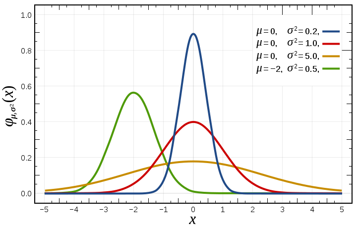
Figure B1.2. Probability density function for the normal distribution (from Wikipedia)
Winds may be classified according to their velocity with the Beaufort scale, which is schematically shown in Figure 4. Please note that by convention wind velocities are mean speed taken at 10 m over the ground and usually averaged over 10 minutes, and do not capture the speed of wind gusts.

Figure 4. Beaufort wind force scale in scale units, knots, and meters/second. By Ldecola - Own work, CC BY-SA 4.0, https://commons.wikimedia.org/w/index.php?curid=74954408.
The Beaufort scale is presented in detail in this Wikipedia page which also shows pictures of the waves that may be originated by each wind speed class. The pictures are extremely interesting to gain a perceptional understanding of the phenomena that may be originated by a given wind velocity.
Another important characterisation of the wind is the gust factor, namely, the ratio between a peak wind gust and mean wind speed over a given period of time. When only measurements of mean wind speed are available, the gust factor allows one to assess the peak wind speed for a given site.
The wind forces acting on a ship largely depend on the geometric behaviours of the ship and its motion. In particular, the windage sided area is an important feature to consider. Windage is the force induced on the ship by friction due to movement of air originated by wind. The windage sided area is the area of the ship exposed to wind (wind side). Wind is usually not a problem when it is lower than Beaufort 4, unless the ship is in ballast (a ship which is empty and is moving from one place to another) or the wind is coming from astern (the rear part of the ship is called stern - the front part of the ship is called bow).
Box 2: Ballast
Ballast is material that is used to provide stability to a ship. A ballast tank within the body of the ship has the capability to store and release water to balance the ship when needed. Ballast is placed below the water level (Figure B2.1).
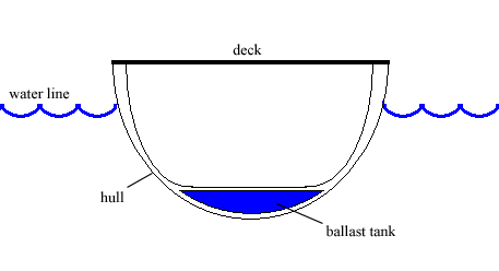
Figure B2.1. Cross section of a ship with ballast tank. By Panscient (talk) (Uploads) - Own work, Public Domain, https://en.wikipedia.org/w/index.php?curid=3619655.
A ship is said "to be in ballast" when it is carrying ballast only. As such, the ship is more exposed to side winds. A ship loading ballast is a ship that is pumping water into the ballast tank to increase stability and to decrease the area exposed to wind.
Wind forces acting on a ship are characterised by complex dynamics. Usually national standards and regulations suggest simplified procedures in particular when referring to moored vessels. As any other simplified method, these standards and regulations should only be used as a guideline for preliminary design, while more refined assessments should be adopted in the final design.
The first design variable to be computed is wind velocity Vw. It depends on climatic behaviors, local orography and geometry of the harbor. The design wind velocity Vw should correspond to the maximum velocity of the gusts that will affect the considered ship. Usually a 30 s gust wind velocity is recommended for use in the wind force equations for mooring analyses, which is about 20% higher than the average wind velocity over a 10-minute period. For moored ships a gust duration of 30 s is sufficient for the full mooring line or fender strains to develop.
When calculating the mooring forces without closer investigation the Spanish standard ROM 0.2-90 (Ministerio de Obras Públicas y Transportes, 1990) recommend to adopt a minimum wind velocity of 22 m/s with a gust factor of 1.2. The same rules suggest to adopt a minimum wind velocity of 17 m/s for mooring operations in normal conditions. Other international standards suggest to adopt a minimum velocity of 30 m/s for computing mooring forces with a gust factor of 1.2 (which correspond to a minimum wind pressure of 0.81 kN/m2, see Figure 5). On the other hand, it is not recommended to exceed a wind velocity of 40 m/s (with gust factor 1.2) which corresponds to a pressure of about 1.44 kN/m2. In fact, if the wind velocity increases above about 25–30 m/s, the ship would normally either leave the berth or take in ballast to reduce its wind area. Therefore, wind velocities above 30 m/s usually are considered precautionary.
The second design variable to be estimated is wind force. The literature suggest standard relationship like, for instance:
Pw= Cw × (Aw × sin2 φ + Bw × cos2 φ) × γw × Vw2/2g (1)
where:
- Pw = wind force in kN;
- Cw = wind force coefficient;
- Aw = side area of the ship above water projected over the ship longitudinal plane, in m2;
- Bw = front area of the ship above water projected over the ship transversal plane, in m2;
- φ = angle of the wind direction to the ship’s centreline (see Figure 6);
- γw = specific gravity of air, 0.01225 kN/m3 at 20°C;
- Vw = velocity of the wind at 10 meters from the ground in m/s; it is recommended to use a 30 s average wind velocity with a gust factor of 1.2;
- g = acceleration of gravity, 9.81 m/s2.
The magnitude of Cw depends on the shape of the ship above the water and the orientation of the ship to the wind direction. As average values of Cw for isolated ships, the following are recommended: for wind crosswise to the ship Cw = 1.3; for wind against the bow Cw = 0.9; and for wind against the stern Cw = 0.8.
For computing Aw and Bw, in absence of known values, the following relationships may be applied:
- Aw = Lbp (G + Z)
- Bw = B (G + Y)
where B and Lbp are the beam of the ship and length between perpendiculars, respectively, G is ship's <a href=https://en.wikipedia.org/wiki/Freeboard_(nautical) target=_blank>freeboard (ship depth-draught)</a>, Y and Z are mean height of the transverse and longitudinal area, respectively, of the ship's superstructure above deck. The maximum wind forces in the above equation is when φ = 90° (i.e. the wind blows perpendicular to the ship’s centreline):
Pw = Cw × Aw × p
where p = γw × Vw2/2g is wind pressure in kN/m2.
Figure 5 shows a schematic of the relationship between wind pressure (horizontal axis) and wind velocity measured at 10 m height for a 10 min period (vertical axis). Reference to those wind conditions is made to be consistent with the wind classification reported in the right vertical axis. When reading the wind pressure, the curve with the gust factor V + 20 % should be selected. Note that the wind force is proportional to the square of the wind velocity, according to the principles of physics.
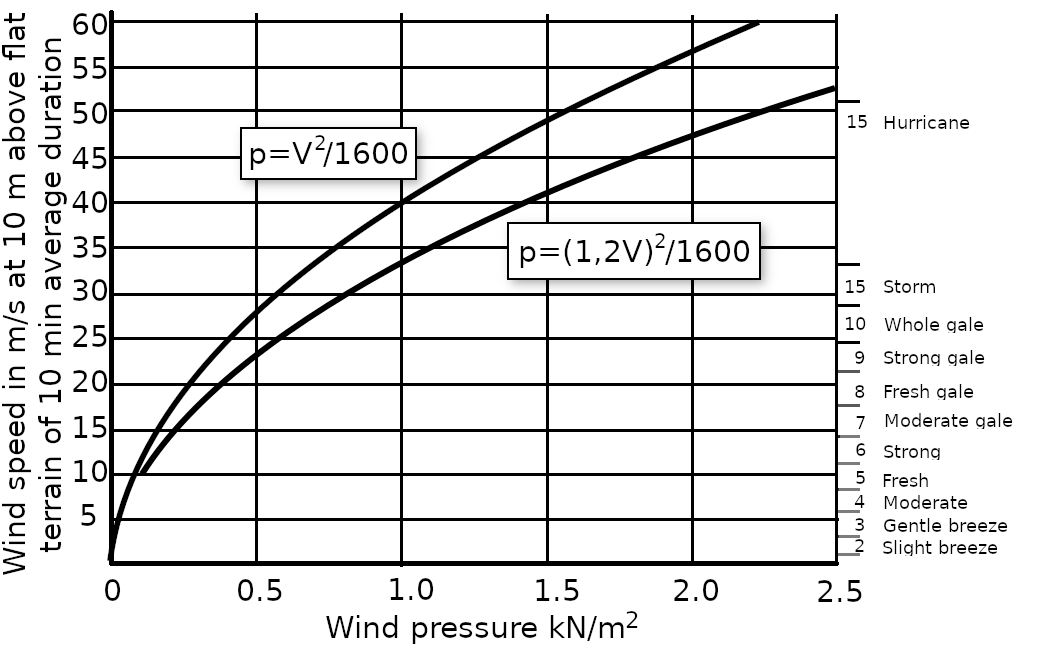
Figure 5. Relationship between wind pressure and wind velocity. Redrawn from Thoresen (2010).
If the wind area is not symmetrical about the midship line, a moment of rotation is induced.
The wind force is given by the product of the considered component of wind pressure by the area of ship above water projected over the longitudinal and transversal plane of the ship (see equation 1). It depends on the ship geometry and ship condition, the latter including ballast load. To give an order of magnitude, Thoresen (2010) points out that a modern cargo ship of 30 000 t displacement, fully loaded, has a wind area of about 15 m2/m of ship in the longitudinal direction, while the same ship in a ballast condition may have an area of about 20 m2/m. Large passenger ships have wind areas of about 35 m2/m or more.
If the wind blows at an angle to the ship, which is the usual situation, there will be a transverse (perpendicular to the boat's side) and a longitudinal load component plus a possible rotational moment (see Section 3.5). The distributed load FdX caused by wind along the direction X on the berth structure over a berth length LQ is equal to
FdX = PwX/LQ (2)
where PwX is the component along X of Pw as given by equation (1).
It should be noted that if a ship protrudes outside the end of a berth structure wind will also cause the turning of the ship around the corner of the berth structure.
The load caused by wind on a single mooring depends on the forcings and the number and position of moors. Mooring forces computation is a complex mechanical problem that is often resolved with simplified methods (see, for instance, here). Proper reinforcing have to be designed to make sure that the load induced by the mooring is effectively distributed along the berth length.
For piers where ships can berth on both sides, the total wind load acting on the pier should be approximately the wind load on the largest ship plus 50 % of the wind load on the ship on the other side of the pier.
Figure 6 shows an example of mooring scheme.
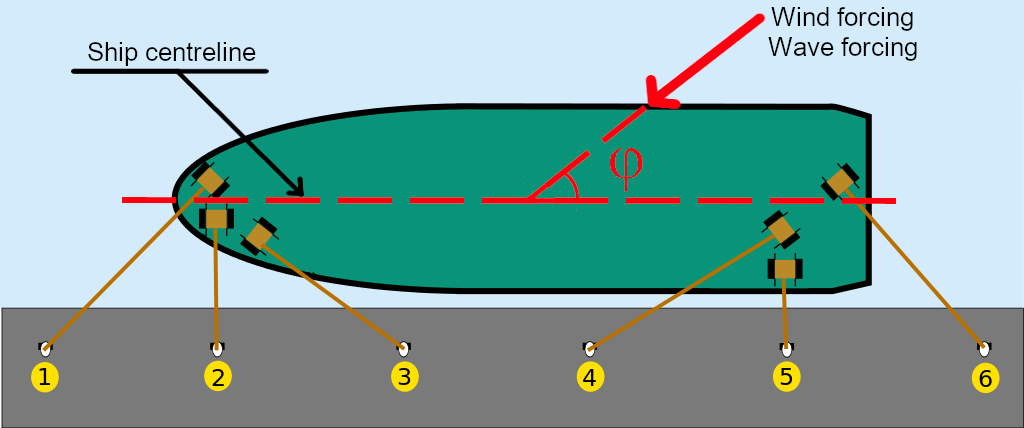
Figure 6. Example of a mooring scheme.
The terminology and function of each mooring line are as follows:
- 1 - Head line: to keep forward part of the ship against the dock;
- 2 - Forward breast line: keep close to pier;
- 3 - Forward spring: prevents from advancing;
- 4 - Aft spring: prevents from moving back;
- 5 - Aft breast line: keep close to pier;
- 6 - Stern line: prevents forward movement;
To properly assess the forcings generated by moored ships exposed to wind or ships exposed to wind during berthing one needs to take into account that the ship may be exposed to rotation. This is especially so for the wind forces acting upon a ship with a large windage sided area.
In general, the action of wind generates:
- Wind drift;
- Rotational moment.
The wind drift is forcing in the direction of wave propagation. To understand the dynamics of vessel rotation we need to define the pivot point: it is the point around which the ship appears to be turning for an observer standing on board the ship. For a resting vessel the pivot point coincides with the center of gravity of the underwater body of the ship. When the vessel moves forward, the position of pivot point shifts forward. For typical velocities of vessels, the pivot point will move to about 1/4th of the length of the vessel from the bow. When the vessel moves astern, the position of the pivot point shifts at about 1/4th of the length of the vessel from the stern.
Rotation is originated when the center of gravity of the windage area does not coincide with the pivot point. From the above consideration it follows that when the vessel is berthing and the speed of the vessel is almost zero the pivot point almost coincides with the center of gravity. If the windage area has the centre of gravity located close to the vertical line from the pivot point there will not be any turning force acting on the vessel (provided that the tugs are pulling with the same force). Therefore the vessel moves only laterally in the direction of the tugs pull. The same consideration apply to mooring forces. If the moored ship is subjected to rotation individual mooring loads should be computed by composing forces.
_all'ormeggio.jpg)
Figure 7. Ship Francesco Mimbelli (D561) at the Mar Grande Naval Station for the Navy Family Day of 14 September 2019. By Michi Abba - Own work, CC BY-SA 4.0, https://commons.wikimedia.org/w/index.php?curid=82603069
Waves in the proximity of ports have different behaviours with respect to offshore. They are often a combination of ocean waves and locally generated wind waves.Therefore they need to be characterised by means of local observations. Very often these are not available, especially for the design of new ports. If it is necessary to make of instrumental recording, it is good practice to install the recording system as early as possible. The very minimum length of the observation period should be 1 year. The length of a satisfactory observation period depends on local wave climate. Usually a period of 5 years is deemed to deliver a useful characterisation.
Wave breaking occurs when the wave crest travels faster than the rest of the waveform. It implies that transfer of energy by waves before breaking is translated in transfer of mass after breaking. Therefore it may generate important local actions and thus conditions for breaking need to be properly characterised. A first approximation of the breaker height can be obtained from the simple expression
db = 1.28 Hb
where db is the sea depth at breaking and Hb is the individual wave height at breaking.
Most berth structures are sheltered against sizable waves. Therefore, the design of berth structures may not explicitly deal with forces and reactions due to wave action, as they are designed against the much higher loads caused by impact and mooring forces.
When there is the need to explicitly take into account wave forces, a relatively reduced wave height is usually adopted as design wave with respect to the expected maximum height for a given return period. In fact, structures are usually resistant to the high loads originated by wind forces and mooring and therefore they are not likely exposed to risk due to wave forcing. Adopting a reduced design wave height may increase the risk of flooding, but this may be justified by the reduced construction costs as long as it does not decrease the safety of personnel.
The characteristics of the waves in a port and their effect on the berthing structure are influenced by the following factors and processes:
- Bathymetry (bottom topography) in the vicinity of the berth structure itself;
- Reflection of waves by the near-shore slopes;
- Refraction of waves the waves enter shallow water at an inclined angle;
- Wave shoaling will influence the design wave heights as the waves enter shallow water.
- Wave regime in the harbour area due to swell and/or wind-generated waves.
Box 3: Rogue wave
Although they do not occur in proximity of ports, which are usually sheltered against extreme waves, it is interesting to note that in open oceans unusually large waves may unexpectedly develop. They are called rogue waves or monster waves. They can be extremely dangerous even to large ships. They are unpredictable as their mechanism of formation is poorly known. They are likely due to the nonlinear superimposition of several waves of different type. They were thought to exist only in legend, because they could not be explained by any mathematical model. Today they are known to occur and in few cases were monitored (see Figure B3.1).

Figure B3.1. A Sign on the USS Lexington that talks about "Rogue waves". By Articseahorse - Own work, CC BY-SA 3.0, https://commons.wikimedia.org/w/index.php?curid=24634674
The design wave is estimated for a given return period, which is defined as the average time lapse between two consecutive events with wave height reaching or exceeding a given threshold. The design return period is usually selected by considering the consequences which originate if the design wave height is exceeded. When human life is at risk the return period is not lower than 100 years. One may also consider a different return periods for different types of functions and types of structures in a port. It is important to point out that design lifetime of the structure that is under design is not necessarily the same as the return period of the design. If the lifetime n years of a structure is selected, then it is assumed that n number of years must pass from building the structure without a situation occurs that exceeds the design load.
Given that waves are governed by random processes the assessment of the design wave is affected by uncertainty and therefore the engineer needs to introduce a cumulative probability of not exceedance P (which may be expressed in percentage) of the given yearly maximum wave height. It is interesting to compute what is the joint probability Pn that the weve height with probability P is exceeded during a period of n years.
First, let us recall the relationship between probability of not exceedance and return period for the maximum annual wave height:

Then, the joint probability that the given wave height is not exceeded in n years is given by:

from which it is possible to get an explicit expression for T:

Figure 8 depicts the relationship between return period of a given wave height, lifetime and probability of exceedance of the wave height during lifetime.
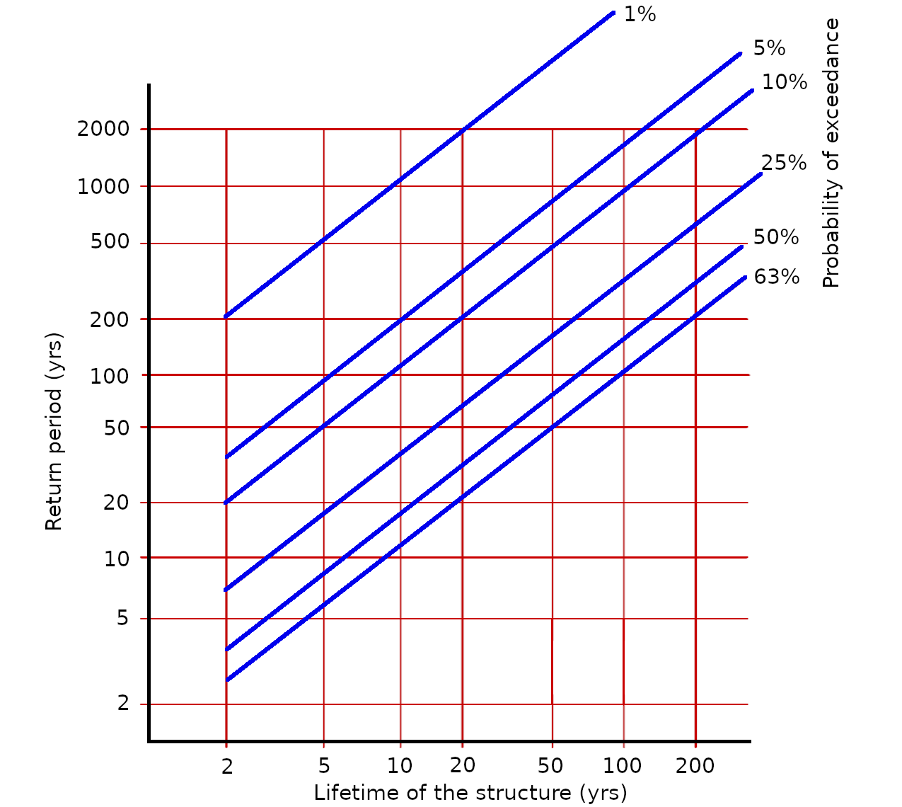
Figure 8. Relationship between lifetime n, probability of exceedance 1-Pn and return period T.
By looking at Figure 8 one can see that a port structure that is required to have a design lifetime of 50 years should be designed for a return period of about 500 years if the probability of exceedance of the design wave during the whole return period is set to 10%. Similarly, by setting the return period equal to the design life one can see that there is a 63% chance of exceeding the design wave height over the given lifetime.
When designing berth structures it is usual practice to adopt a return period for the design wave of at least 100 years. In any case, the return period should be not less than the design life of the structure. If the impact from failure of the structure is unacceptable then a return period of no less than 1000 years should be adopted.
Sometimes guidelines may also recommend to size port structures by referring to the significant wave height, that is, a measure of the sea state was historically chosen to correspond to the intuitive visual measure of the wave height by seafarers. One way to define the significant wave height Hs is the average height of the 1/3 of the highest waves (H<sub>1/3</sub>). Another definition of H<sub>s</sub> is four times the standard deviation of the sea surface elevation.
Quoting from Wikipedia:
Generally, the statistical distribution of the individual wave heights is well approximated by a Rayleigh distribution. For example, given that Hs is 10 metres (33 feet), statistically:
- 1 in 10 will be larger than 10.7 metres (35 ft)
- 1 in 100 will be larger than 15.1 metres (50 ft)
- 1 in 1000 will be larger than 18.6 metres (61 ft)
This implies that one might encounter a wave that is roughly double the significant wave height. However, in rapidly changing conditions, the disparity between the significant wave height and the largest individual waves might be even larger.
Therefore, according to the above statistical assumptions and referring to a sample of block maxima like the annual maximum wave height, one may conclude that the return period of the significant wave height and 1.5 wave height may approximately be, respectively, 10 years and 100 years (see Figure 9).
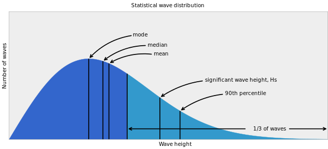
Figure 9. Distribution of wave height. By NOAA - NOAA UCAR COMET ProgramRegenerated using python matplotlib and illustrator, Public Domain, https://commons.wikimedia.org/w/index.php?curid=20498122
The design should also take into account if permanence of berthed ships is foreseen for any condition or for limit permanence conditions. In the latter case, ships are unberthed - or other conservative actions are taken - if limiting conditions are reached. Tugs availability is to be verified accordingly to make sure that ships an be safely unberthed.
For permanence in any condition, the design wave height is computed for each considered wave direction and the structures sized accordingly. For permanence allowed until limiting conditions only, the values for wave height specifically defined as limit conditions should be adopted. A probability - return period - should be anyway associated to the design wave to be used in cost-benefit analyses. Limiting conditions are usually defined in terms of maximum acceptable pressure over the fenders, ship's hull or others.
As a rule of thumb, the Spanish standard ROM 0.2-90 (Ministerio de Obras Públicas y Transportes, 1990) suggests that the following values should be adopted as significant wave heights for permanence limits of moored ships (of course if the extreme significant wave height should be adopted if it is smaller):
- Ships with up to 3000 t displacement:
- Pleasure craft, H = 0.40 m;
- Fishing vessels with length overall less than 30 m, H = 0.60 m;
- Fishing vessels with length overall higher than 30 m, H = 1.00 m;
- Other types of ship, H = 1.00 m;
- Ships with displacement greater than 3000 t:
- H = 2.00 m.
Wave forces on a moored ship are originated by the movement of the ship that is caused by wave action. The ship is a rigid body with six degrees of freedom (see Figure 10). In fact, the motion of a ship at sea has the six degrees of freedom of a rigid body, corresponding to translation along the three directions of space and rotation around them.
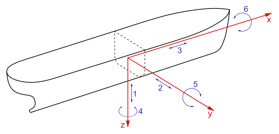
Figure 10. The six degrees of freedom of movement of a ship. By Brosen - Own work, CC BY 2.5, https://commons.wikimedia.org/w/index.php?curid=777358
Once are impacted by waves, ships can undergo a rotational and/or translational motion. We can identify three axes in any ship: longitudinal, transverse and vertical axis. The rotational movements around them are roll, pitch, and yaw respectively (see Figure 11, left panel). The translational motions along the three axes are surge, sway and heave, respectively (see Figure 11, right panel).


Figure 11. Rotational (left) and translational motion of a ship. Left: by Original uploader was Jmvolc at en.wikipedia - Transferred from en.wikipedia to Commons by User:Waldir using CommonsHelper., Public Domain, https://commons.wikimedia.org/w/index.php?curid=15243568; right: By Jmvolc at English Wikipedia - Own work, Public Domain, https://commons.wikimedia.org/w/index.php?curid=77832248.
Wave forces are originated by complex and definitely non-linear dynamics. Forces and mooring system reactions arise from interaction of moving water particles, ship motion induced by waves and mooring system response. Wave forces depends on many variables including:
- Characteristics of the incident wave action, in terms of wave type, height, period and direction;
- Configuration of the berth and type of structure;
- Elastic characteristics of the fenders and mooring lines;
- Ship characteristics;
- Type of ship movement.
Wave forces on moored ships are originated by two distinguished but interacting processes. The first is rotational and/or translational oscillation of the ship induced by an oscillating force at the frequency of the waves. Oscillation may take place along and/or around each of the three directions of space.
The second type of wave force is called the drift force and is a net force in the direction of wave propagation. Wave drift forces are due to absorption or reflection of waves. Waves carry momentum, when structures like ships modify the behaviors of the wavefront and its momentum a reaction force is originated. The drift force is a steady force in regular waves and a slow-varying/low frequency force in irregular waves. Because the usual range of periods of these low frequency forces (20–100 s) is also within the range of natural periods of moored ships, the slow-varying drift force may cause overstressing of mooring lines and large fender forces. Analytical and computational and physical modelling techniques can be used to approach the general moored-ship problem.
To better understand the general behaviour of the stresses originated by waves on a moored ships the following guidelines may be useful (Thoresen, 2010):
- mooring line forces are induced almost entirely by waves of period longer than 20 s, with major contributions occurring in the period range 40–200 s;
- rolling is triggered primarily by swells with period in the 13–19 s range;
- pitching is small and insensitive to the wave period, whereas heave motions tend to equal the wave height at long periods and are smaller with short-period waves.
Analytical assessment is very complex and therefore small scale models tests are usually carried out. An interesting example is presented in this video taken in the laboratory of Deltares in Delft.
For preliminary design empirical relationships may be used to provide rule-of-thumb values.The Spanish standard ROM 0.2-90 (Ministerio de Obras Públicas y Transportes, 1990) recommends that the wave forces or pressure on a ship may be preliminarily estimated by using the following relationships:
Lateral or transverse wave force in kN: FTwave = Cfw × Cdw × γw × Hs2 × D′ × sin2 φ
Longitudinal wave force in kN: FLwave = Cfw × Cdw × γw × Hs2 × D′ × cos2 φ
where:
- Cfw = waterplane coefficient depending on the wave length Lw at the location and the ship’s draught D; values from Figure 11, left, are suggested [dimensionless];
- Cdw = depth coefficient depending on the wave length Lw and the water depth at the location; values from Figure 11, right, are suggested [dimensionless];
- γw = specific weigth of water (seawater, 1.034 t/m3; freshwater, 1.00 t/m3) [force/length3];
- Hs = design significant wave height [length];
- φ = angle of the wave direction to the ship’s centreline (see Figure 6) [dimensionless];
- D′ = projection of the ship length in the direction of the incident waves. D′ = Lbp × sin φ + B × cos φ [length];
- Lbp = length between perpendiculars [length];
- B = beam of the ship [length];
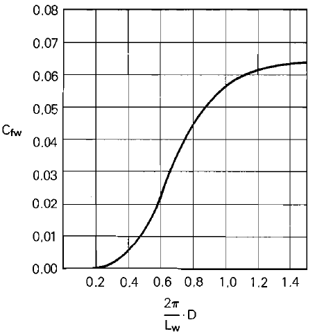

Figure 11. Values for coefficients Cfw and Cdw. From Spanish standard ROM 0.2-90 (Ministerio de Obras Públicas y Transportes, 1990). D is the draught of the ship, h is water depth at the location and Lw is wave length at the location.
Long waves, also called waves of long period, are those characterised by periods longer than 20-30 s and low amplitude. Once they enter into the confined area of the harbor they may induce singular conditions if their long period is close to the natural oscillation period of the harbor itself. In particular, it may happen that the oscillation period of harbor areas induced by long period waves is close to those of surge, sway and yaw motions of moored ships. Due to the lower attenuation of waves in this typical frequency range, dynamic amplification may occur with increase in mooring forces. Such increase is much difficult to quantify due to the non-linearity of the system. The mitigation of this undesired effect relies on anticipation and mooring and habour configuration in order to avoide resonance. Knowledge of the natural oscillation period of the bay, the long period of waves and oscillation period of moored ships is necessary. Table 1 provides indications on likely natural oscillation period of moored ships (see also Spanish standard ROM 0.2-90 (Ministerio de Obras Públicas y Transportes (1990), pag. 215-216). The lesser the ship's mass the shorter the natural oscillation period. Keep in mind that the influence of load conditions is very strong. Fully loaded vessels have longer period. Also, the values in Table 1 are valid for elastic mooring lines and normal fenders. Rigid moorings and fenders reduce the period.
| Ship type | Pitch | Roll | Heave | Sway | Yaw | Surge |
| Pleasure and shifting craft | 2-4 | 3-5 | 6-9 | - | - | - |
| Small freighters (< 7000 DWT) | 5-8 | 7-10 | 7-10 | - | - | - |
| Freighters (7000-11000 DWT) | 7-11 | 9-14 | 10-11 | - | - | - |
| Passengers liners | 12-14 | 16-18 | 9-12 | 14-32 | 15-20 | 45-85 |
| Oil tankers (30000 DWT) | 7-9 | 9-12 | 12 | 14-32 | 15-20 | 45-65 |
| Oil tankers (100000 DWT) | 8-11 | 10-14 | 15 | 40-55 | 25-50 | 70-85 |
| Oil tankers (300000 DWT) | 9-12 | 12-16 | 17 | 50-100 | 50-100 | 100-115 |
Table 1. Characteristic periods in seconds for given ships.
Breaking waves against vertical walls can create considerable forces of the order of about 150–600 kN/m2. Therefore, in the design of berth structures one should try to prevent breaking waves against the berth, and for quay structures the loading platform should be higher than the crests of the waves.
Currents can arise in a port basin with significant velocity due to several possible reasons including:
- wind forces transporting water;
- temperature and salt content gradient;
- tidal effects;
- water flow from river estuaries.
The action of current upon a moored ship can produce three types of forces: pressure forces, drag forces and forces induced by dynamic instability. The latter is given by lateral self-excited oscillations that produce the so-called "flutter effect". Flutter is a dynamic instability of an elastic structure in a fluid flow, caused by positive feedback (resonance) between the body's deflection and the force exerted by the fluid flow. Friction forces are generally neglected except when current flows in a direction that is parallel to the ship's longitudinal axis.
For the purpose of design the resultant forces on the ship can be simplified into one horizontal force in the longitudinal direction of the ship, another in the transversal direction and a vertical axis moment, all of them approximately applied at the ship' center of gravity. Current forces on a ship, and in particular the longitudinal forces, depend on type and size of the ship and morphology of the port basin. The current forces increase for increasing clearance beneath the keel (distance between keel bottom and sea bed). When designing the moorings the current forces should be added to wind forces.
When designing new berth structures, it is recommended to make sure that the berth front is directed as parallel as possible to the prevailing current. Since the direction of the current can vary, it is also necessary to assess over a long time period the current perpendicular to the direction of the berth front. If such a component reaches a value of about 0.5 m/s the berthing operation would be difficult.
It is also important to estimate the forcing induced by currents during the construction phase, when temporary conditions may be particularly unfavorable for both underwater and above water works.
The Spanish standard ROM 0.2-90 (Ministerio de Obras Públicas y Transportes, 1990) recommend the following empirical relationships for estimating current forces due to pressure (please refer to the linked document for more details on forces induced by drag):
FTC = γw/(2g) CTC VC2 ALC sin φ
FLC = ± γw/(2g) CLC VC2 ATC
MTC =FTC E = FTC KEC L
where:
- FTC is the transversal component (perpendicular to the boat's side) of the current force on ship;
- FLC is the longitudinal component of the current force on ship. Its magnitude is assumed to be independent of φ so the positive or negative sign should be selected accordingly;
- MTC is the rotational moment at the ship's center of gravity;
- γw is specific weight of water (1.024 t/m3 for salt water);
- g is gravity;
- φ is the angle between the ship centreline, considered from stern to bow, and the direction of the current. If studies on current direction are not available one should assume that currents in any direction may occur;
- VC is the design horizontal current velocity at a depth of 50% of the ship's draught. It is considered to be constant along all the depth (m/s). Velocity for limiting permanence conditions should be considered when ships are planned to unberth in critical conditions. As a rule of thumb, limiting conditions may be given by VC = 1 m/s for cross currents and 2.5 m/s for bow or stern current;
- CTC is a shape factor for the calculation of transverse currents. It depends on the ratio of water depth/ship draught, increasing as this ratio approaches 1. CTC varies from 1 for deep water and 6 for unit value of the above ratio;
- CLC is a shape factor for the calculation of the longitudinal current force on a ship (dimensionless). It depends on the geometry of the ship's bow. It can vary between 0.2 and 0.6, the latter extreme being suggested for conventional bows as a conservative value;
- ALC is the submerged area of the ship exposed to current projected over the longitudinal plane (m2);
- ATC is the submerged area of the ship exposed to current projected over the transversal plane (m2);
- E is eccentricity of the transverse component FTC with respect to the ship's centre of gravity;
- KEC is the eccentricity coefficient, varying from -0.17 to 0.17;
- L is ship length.
Note that the dependence of FLC on the attack angle of the current is neglected to simplicity.
Impact of ships is an accidental load due to the failure of standard berthing procedures. The accidental berthing load due to ship collision with the berth should be estimated by assuming that the energy transferred to the berthing system is twice that which is computed for normal operating conditions. In turn, the latter is computed when estimating the berthing load. We are not discussing the berthing load in detail here. We just mention that it can be computed by assuming that the berthing structure - and eventually the fender system - is subjected to the impact forces that coincide with the reaction corresponding to the kinetic energy that is transferred to the resistant structure.
Spanish standard ROM 0.2-90 (Ministerio de Obras Públicas y Transportes, 1990).
Thoresen, C. A. (2010). Port designer's handbook. Thomas Telford.
Download the powerpoint presentation of this lecture
Last change on March 19, 2024.
- 1789 views
