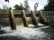
We discuss here the hydraulic design of river barrages for water withdrawal. These infrastructures are frequently designed to serve small hydropower plants or water supply systems. According to the Italian regulation, retention structures over rivers are classified according to the following categories:
- Concrete or stone masonry dams;
- Earth dams;
- Other types of dams;
- River barrages.
A river barrage is a low-head diversion dam that is built to allow diversion of a part of the water flow. The barrage determines a little increase of the upstream water profile and a little upstream reservoir. The purpose of the barrage is essentially to stabilize the upstream water level and the river profile in order to ensure a long technical life to the diversion facilities. We can often see in mountain rivers small barrages that are not finalized to water withdrawal but just to bed profile stabilization. These structures are called check dams while the term "barrage" usually identifies structures finalized to water diversion. Barrages are not finalized to regulate the river flow beyond the daily time scale, while dams are intended for annual and interannual regulation.
In Italy dams are defined as structures that are either more than 15 meters high, where the height is measured from the lowermost above ground to the uppermost part of the structure that can be surmounted by water, or originating an upstream storage of more than 1.000.000 m3, where storage is measured at the highest regulation level. These infrastructures must be built according to strict procedures and are monitored by National bodies. Therefore, when designing barrages one usually takes care of not exceeding the above limits.
Design of barrages depends on several factors that depend on the behaviours of the river bed, the geology of the surrounding area, the presence of mechanical regulation, the bed load, the presence of floating material during floods, the fish population and the river ecosystem in general. Usually barrages are straight structures that are displaced perpendicularly to the main flow direction, but in some cases they can be displaced at an angle, in order to increase the length of the structure therefore lowering the water depth over the barrage.
Barrages are usually classified into the following categories:
- Regulated barrages, which are equipped with machineries like gates or regulated sluiceways to keep the upstream water level stable;
- Unregulated barrages, when regulation of the upstream water level is not possible;
- Temporary barrages.
Figure 1 shows a satellite view of the regulated barrage Ybbs-Persenbeug on the Danube River. One can easily identify the gates in the central part and the navigation locks in the proximity of the river embankments.
Figure 1. Aereal view of the regulated barrage Ybbs-Persenbeug on the Danube River. Water flows from the left to the right. One can identify the upstream port, the navigation locks, the hydropower facilities, the gates and the "Porte Vinciane", namely, lock gates.
We will consider here the design of unregulated barrages, which are also called "fixed barrages".
River barrages are often used to serve run-of-the-river hydropower plants, which operate without regulation of the river flow (or with little regulation at the daily time scale). They are often built in mountain rivers and therefore they need to be designed with particular care to minimise their impact on the ecosystem and to minimise the related risks. In fact, these structures may increase flood risk and may induce instabilities along the hillslopes. We will discuss the hydraulic design only and therefore will not consider issues related to the structural design.
The first problem that one needs to solve is the estimation of the design flow. One needs to evaluate the water demands, by considering the water system that is going to be fed by the diverted flow. If the design flow is conditioned by water availability, rather than water demand, as it often occurs, the design flow is estimated by looking at the flow duration curve.
We already know that estimating water resources availability is a complicated problem. Hitherto we discussed the estimation of the flow duration curve by using observations and rainfall-runoff modelling. We will discuss here an additional quick method to be used when observations are not available, which makes use of the concept of hydrologic similarity. The procedure is based on the assumption that the hydrological regime in the river cross section of interest is similar to that of a gauged section for which a flow duration curve is available. Then the flow duration curve (FDC) of interest is obtained by rescaling the FDC of the gauged location through the relationship Aug/Ag, where Aug and Ag are the catchment areas at ungauged and gauged locations, respectively.
Another opportunity to estimate the FDC for ungauged locations is to make use of regional approaches. The method requires the preliminary estimation of a so-called "homogeneous region" where we assume that the FDC in every river cross section is given by a parametric equation. Then, the related parameters are estimated for all the gauged sections in the homogenous region and regression relationships are identified to estimate them depending appropriate hydrological, morphological and climatic behaviours of the contributing catchment. Such behaviours are selected basing also on their easy availability for all the catchments into the homogeneous region. The procedure is subsequently validated by reproducing the FDC for the gauged sections by using a leave-one-out procedure. Namely, the gauged locations are one-by-one treated as if they were ungauged. An example of application is given by the scientific paper that is available here.
We already discussed empirical criteria to estimate the design flow from the flow duration curve. For small hydropower plants a first estimate can be quickly obtained by taking the flow with duration ranging from 30 to 60 days. In the executive design the maximum diverted flow (the design flow) is to be determined through a cost-benefit analysis, by also considering the social impact and the environmental impact of the plant.
Once the design flow, Qp, is estimated, one can compute the average withdrawn flow Qmp and the following indexes:
- Water withdrawal index Ic=Qp/Qm, where Qm is the average river flow in the undisturbed situation
- Water use index Iu=Qmp/Qm.
Figure 2 presents the typical structure of a unregulated river barrage. We can identify the following features:
- Main spillway: it is the spillway that releases the excess water flow with respect to the environmental flow and the diverted flow. The main spillway may be lowered in its central part to keep the main flow far from the hillslopes. If there is a lower section of the main spillway, which in Italian is called "gaveta", it is connected to the upper parts of the spillway through the so-called "wings", which have a slope of 100% (45°).
- Environmental flow spillway (called "callone in Italian): it is the spillway located at the lowest level, which releases the environmental flow. It is located at the lowest level to make sure that the environmental flow is the highest priority release from the barrage. It is usually 40-50 cm wide and local laws may impose that it is not equipped with gates, to avoid interruption of the environmental flow.
- Withdrawal spillway: it is the spillway releasing the diverted flow. It is usually equipped with gates to allow cleaning and maintenance of the diversion facilities. Figure 5 shows a case of diversion through a lateral spillway, but in some cases it can be located in the body of the main spillway. Small diversions may be obtained by placing a grid in the body of the main spillway.
- Gravel trap and sand trap: they are displaced in line to allow the separation of gravel and sand that are floated by the diverted flow. They are equipped with a overflow spillway and and a flushing sluiceway to allow cleaning and maintenance. The sand trap may be divided into two longitudinal channels in order to allow alternate cleaning to ensure continuous functioning of the infrastructure.
- Upstream tank: the upstream tank may be needed if water is conveyed downstream with a pipe. In fact, to avoid the entrance of air into the pipe the upstream tank is designed to keep the water level sufficiently higher than the upper ceiling of the pipe in any working conditions.
- Protections of downstream erosion: boulders can be placed downstream the barrage to make sure that the river bed is not eroded by the high energy flow from the main spillway. In alternative pools, or check dams, may be displaced immediately downstream the main spillway.
The structure of the barrage includes the longitudinal walls, the foundations and any other structure that may be needed to ensure stability to the barrage. 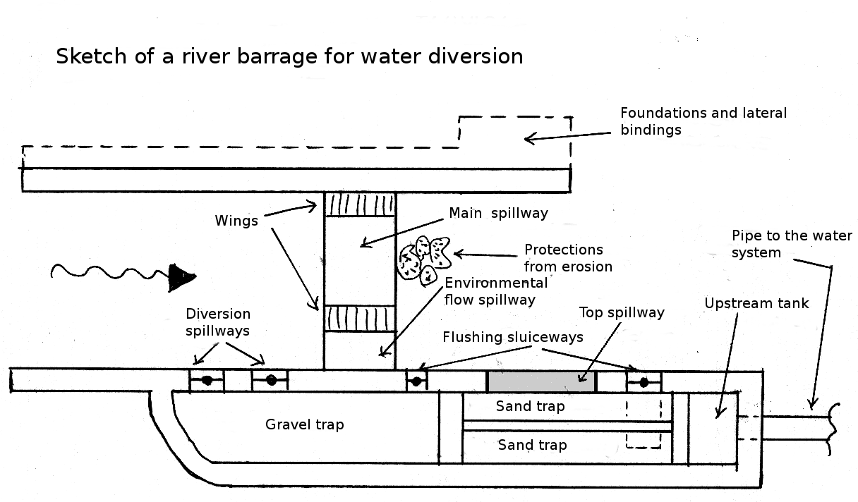
Figure 2. Sketch of a typical unregulated river barrage
The elevation of the barrage over the river bed, should be determined by considering the following issues:
- The barrage should induce an upstream increase of the flow depth so that a small reservoir forms to ensure a daily compensation of the mismatch between water demands and water availability; the volume of the reservoir should be limited and in any case not greater than 1.000.000 m3, to avoid the infrastructure to be under the jurisdiction of the National authority for dams.
- The barrage should not exceed the height of 15 meters, measured from the foot of the foundation to the upper spillway's threshold. This requirement is also dictated by the need to avoid the infrastructure to be under the jurisdiction of the National authority for dams.
- The upstream water profile should not induce an increase of the risk of flooding. Such evaluation should be carried out by estimating the surface profile of the river flow, by assuming gradually varying hydraulic conditions and a suitable design hydrograph.
- The barrage should not compromise the stability of the river bed and the hillslopes. An accurate evaluation of local geology is needed in order to make the required verifications.
- The sediment transport associated to the river flow must be evaluated to avoid a rapid siltation of the barrage. Uncertainty needs to be taken into account and management strategies to ensure cleaning should be designed.
The above considerations are useful to determine the elevation of the main spillway of the barrage. With respect to such elevation, the diversion spillway and the environmental flow spillway should be positioned at lower elevation, in order to give higher priority to the respective flows with respect to the water flow above the main spillway. In fact, the latter is designed to ensure that the river flow exceeding the environmental flow and the diverted flow is efficiently and safely conveyed downstream.
The difference in elevation between main spillway and diversion spillway is computed by assuming that the flow Qp through the diversion spillway, namely, the design flow for the barrage, can be calculated according to the relationship

where μ is the spillway coefficient, which is frequently assumed as 0.385 for spillways with large threshold, Δh1 is the elevation difference between main and diversion spillways, g is gravity acceleration and Lp is the total width of the diversion threshold.
In the same way, the elevation difference between diversion spillway and environmental flow spillway is computed through the formula

where QDMV is environmental flow and Lc is the width of the environmental flow spillway. While the latter should not be equipped with gates, the diversion spillway should be, and the related gates may be remotely controlled, to regulate the diverted flow and to close the diversion during high flow periods when the water may be not sufficiently clear, and to close the diversion when cleaning of the infrastructure is needed.
Gravel and sand traps should induce the settlement of suspended material which cannot be conveyed downstream along with the diverted flow. In fact, suspended material may induce siltation in downstream channels and may damage hydraulic machines like turbines. The producer of the machines generally specifies the maximum size of sediments that are allowed to be routed through. In what follows we will assume that the suspended material is formed by spherical particles whose limiting diameter is d.
The gravel trap should induce the settlement of the coarser sediments. It's width and longitudinal length are about 2-6 meters and 5-10 meters, respectively, while the water depth is about 50-70 cm. Usually the gravel trap is about half long, in the longitudinal direction, with respect to the sand trap, whose design procedure is described below. The actual size of the traps of course depends on the design flow and the limiting size d of the suspended material that is tolerated downstream. The gravel trap is separated by the sand trap by a low-crested weir, which is generally permanently submerged and is about 40-50 cm high. Before the weir we need to locate a bottom discharge to ensure the periodic flushing of the settled material.
The sand trap can be subdivided in two longitudinal and separated channels. The water depth in the sand trap is still of the order of 50-70 cm and the width is about 2-6 metri for each channel. The length of the sand trap is designed to ensure that water remains into it for a sufficiently long time to allow the settlement of spherical particles with diameter d that may be suspended in the proximity of the water surface. If the water depth in the sand trap is h, the time needed to the above particle to settle is computed as t = h/ws, where ws is the sedimentation velocity which is given the by the Stokes formula. The latter is derived by equating the weight of the particle, which tends to sink the particle, with the hydrodinamic force that tends to oppose sinking. The steps to derive an explicit relationship for ws are presented here below.
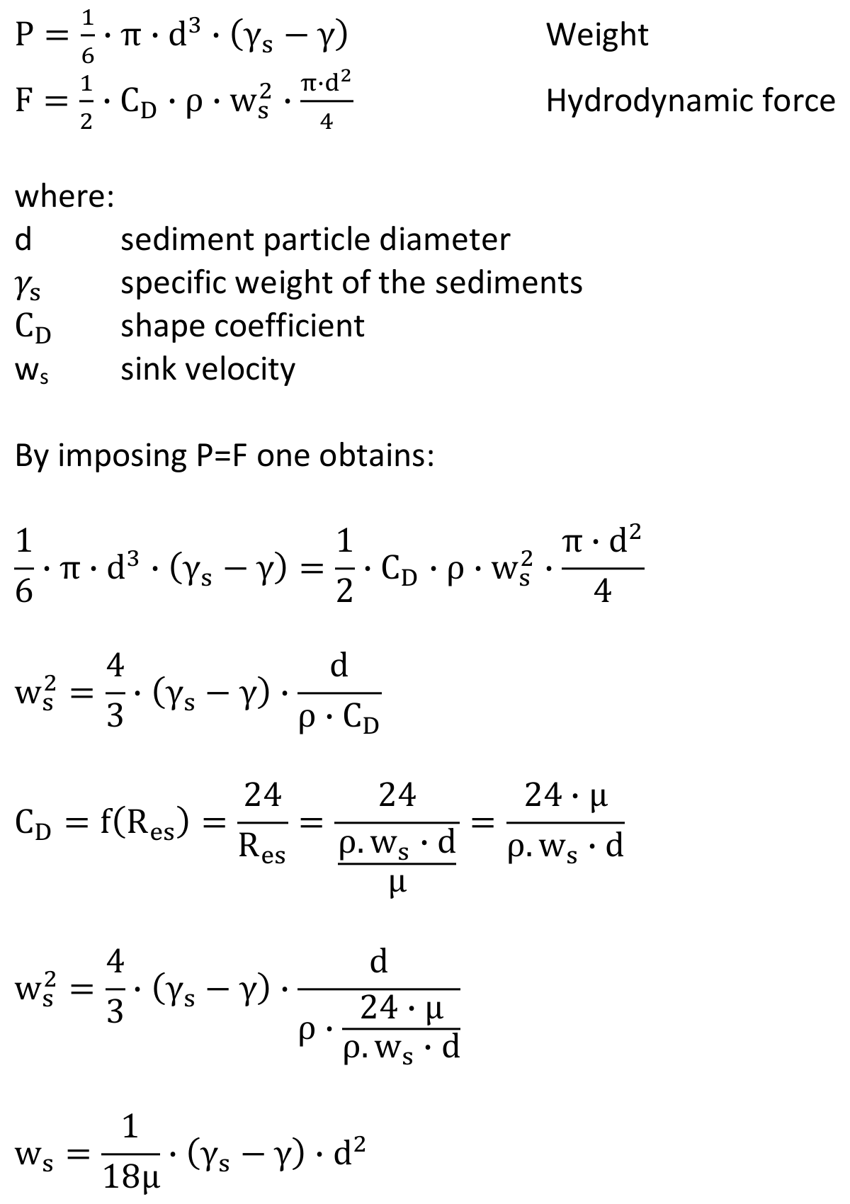
Depending on the width of the sand trap and water depth inside it it is possible to compute the area Ad of the cross section of the sand trap itself and therefore the velocity V = Qp/Ad of the flow. One needs to check that such velocity is in the range 0.05-0.15 m/s, to make sure that turbulence is avoided. Therefore, the length Ld of the sand trap is given by Ld = V t. An order of magnitude is provided by the empirical relationship L = h/0.06. At its end, the sand trap is separated by the head tank, if present, or the adduction structures by a low crested weir whose height is 40-50 cm. Another bottom discharge is placed before the weir to allow periodic flushing. A grid may also be placed here to remove floating material.
The head tank is designed so as to ensure that the adduction pipe is always sumbmerged. Usually one adopts a geometry that ensures that the elevation water profile always exceeds the upper elevation of the adduction pipe by 1.5 va2/(2g), where va is the upper value of the flow velocity in the adduction pipe.
When high flow may occur over the main spillway it is advisable to adopt a geometry of the main spillway itself that ensures that water is accompanied downstream to avoid the detachment of the water current from the underlying structure. In fact, the repeated detachment and subsequent impact of water may damage the structure. It is therefore suggested to use an adequate profile for the weir, for instande by adopting the Creager or Scimemi profiles. An analytic and graphic representation of the two profiles is given here. The web page is in French but figures and formulas are easily understandable.
It is also advisable to check the barrage against piping, namely, the infiltration of water under the structure which originates a water flow under the foundation (seepage), which rapidly would induce failure of the structure itself. An empirical approach is provided by the Bligh-Lane relationship:
F > h/(Lv+1/3 Lh)
where F is a coefficient for which the literature provides reference values depending on the type and size of river bed material. Figure 7 shows a transversal section of the barrage along the main spillway. The position of the environmental flow spillway is also highlighted, along with the horizontal and vertical flow paths to be considered when applying the Bligh-Lane formula.
If safety against piping is not ensured, cut-off walls can be built to increase the length of the seepage path (see Figure 3). Cut-offs to prevent seepage and/or internal erosion are an integral part of many dam and levee remediation projects. Several technologies may be used to construct cut-offs through levees and below structures like dams or barrages. These technologies can be broadly classified into three main categories:
- cut-offs created by backfilling a trench or shaft excavated under a bentonite slurry or similar supporting medium;
- cut-offs created by mixing the fill and/or foundation soils in situ;
- cut-offs created by using sheet piles (see Figure 4).
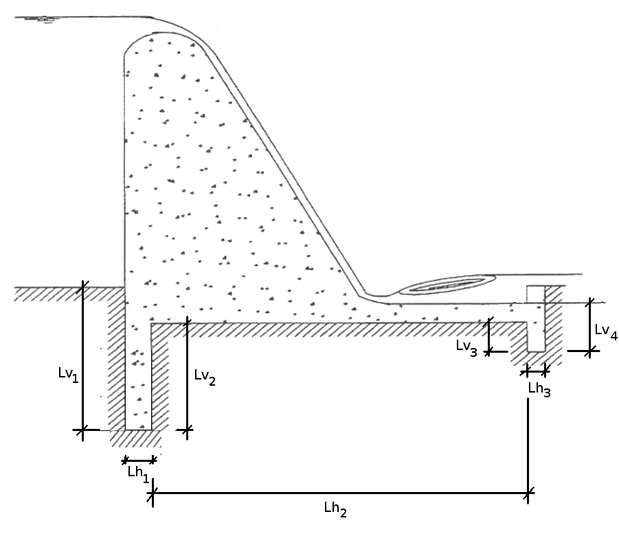
Figura 3. Transversal section along the main spillway of a river barrage equipped with a Creager profile.
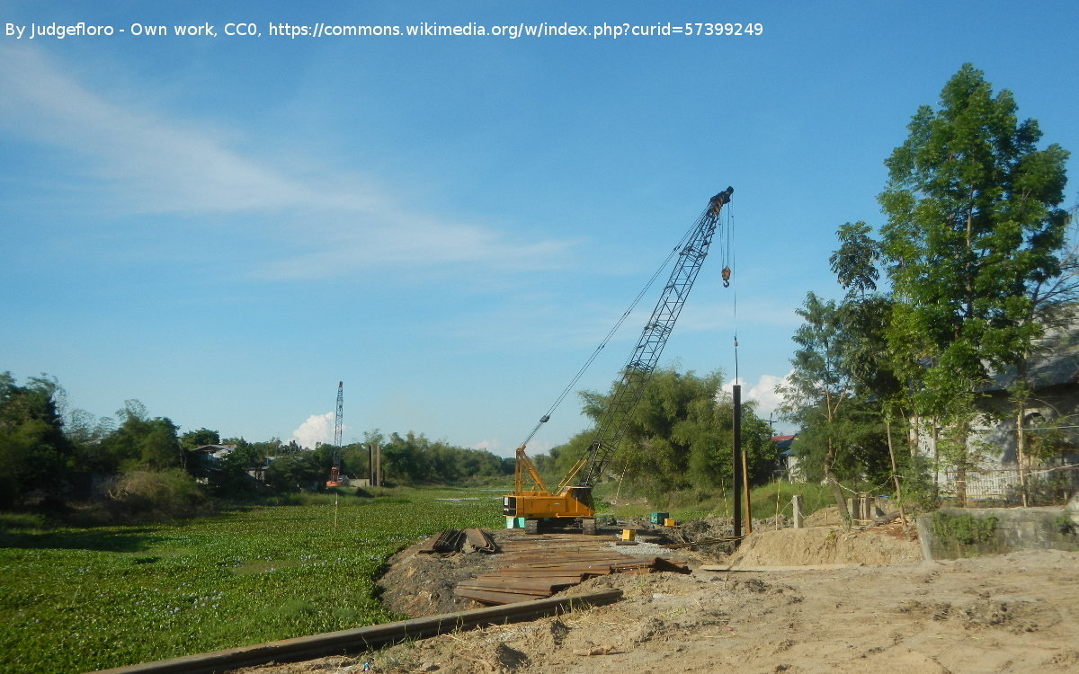
Figura 4. Cut-off with sheet piles.
Finally, it is appropriate to protect the downstream river bed against erosion, by placing a dissipative basin and/or boulders of appropriate size.
Last modified on April 3, 2020
- 821 views
